“A majority of the shots traveled along with the speeders, sometimes with framing that favored the sky to include tie fighters in the shots,” discusses Cheng. “We were able to depict the action pretty easily, given the planning and the planar environment we knew we were working with.”
One aspect of the battle that featured highly in the previs was the red dust effect kicked up by Resistance fighters and in crashes; it was also an important element to reveal in the scarring of the ground. “To simulate the effects in previs,” says Cheng, “we created particle instance effects in Maya that we could attach to the speeder blades for both the rooster tail red dust that gets kicked up as well as the trail lines that represented the ground scarring. The red dust and trail were particle emitters that spawned a variety of sizes of red rocks to which we could adjust the density, direction and speed.
We also had red mist particle sprites for very fine dust to help sell it,” adds Cheng. “For the ground churn, separate emitters would spawn red rocks onto the ground surface along with larger white rocks to help represent the raking effect and give the trails a bit more visible volume. Overall the effect worked very well and allowed our artists to animate the vehicles the way they wanted during previs while the particle emitters just did their thing.
Techvis rounds out The Third Floor’s work
In addition to previs and postvis, The Third Floor delivered techvis for some sequences. This was designed to aid in visualizing how certain scenes could be captured, how sets were constructed and what the visual effects process might then involve.
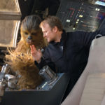
Techvis was particularly helpful with envisioning cockpit shots for the battles in space and on Crait. Artists at The Third Floor oftentimes even worked from the same art department CAD models that were used to build all of the practical ship cockpits and gun turrets. “We also used models of each designated stage at Pinewood Studios,” says Cheng, “so we knew what the clearance and dimensions were and could help work out the camera placement and movement for each shot confidently.”
A typical techvis delivery included animated Quicktime diagrams, usually in plan view, which encompassed the movement of the camera, lens, frustum and the camera’s visible path, along with the relevant dimensions and speeds. “To provide context,” details Cheng, “we also included picture-in-picture of the previs shot as approved, as well as the view through the techvis camera, which helps validate the techvis.
As is often the case, continues Cheng, “sometimes you need to do camera cranes that are tricky when working with stationary cockpits where there is both camera movement and implied vehicle movement over distance. In addition to accuracy, clarity is really important for techvis. It’s easy to overwhelm with information, so we like to make sure to clearly show what the camera is doing in the shot while providing the most relevant info.”


 Read more about the visual effects of Star Wars: The Last Jedi in